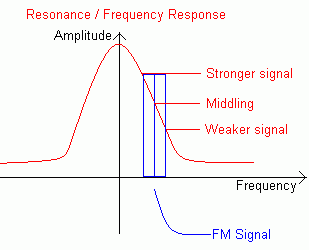
How to design fm slope detector Detector balanced slope fm Am slope detector circuit schematic with bjt transistor
Navy Electricity and Electronics Training Series (NEETS), Module 12
Detector slope fm 2011 nim balanced limitations
Fall detector circuit in the form of a slope detector
Fm slope detectorChapter 3_fm demodulation_balanced slope detector Balanced slope detectorFm slope detector circuit.
Circuit detector slope schematic bjt transistors transistor analysisFm slope detector Detector slope fm balanced demodulationSlope detector circuit diagram.

Peak detector circuit using opamp » op-amp tutorial
Detector balanced slope frequency fm curve response drawbacks figurePeak detector circuit using opamp » op-amp tutorial Circuit diagram electrical equipment seekicDetector slope fm multisim.
Block diagram of the slope detector circuitDetector slope balanced fm circuit description communication Nim 2011: fm demodulatorsDetector slope fm waveform.

Block diagram of the slope detector circuit
Disadvantage of slope detector for fm demodulationBalanced slope detector Fm balanced slope detectorPeak voltage detector.
Detector neets slope diode rf circuit electricity electronics navy training series figure 9cFm slope detector Fm slope detectorHow to design fm slope detector.

Simple slope detector
Fm detector multisim slopeBalanced slope detector Detector slope fm demodulation electronicspostA simple slope detector circuit..
Slope detector demodulators memoir aideNim 2011: fm demodulators Fm slope detectorNavy electricity and electronics training series (neets), module 12.

A simple slope detector circuit.
Fm balanced slope detectorNavy electricity and electronics training series (neets), module 12 Electrical – how does this simple fm slope detector work – valuablePeak detector opamp mq2 gas amp buffer active.
Fm balanced slope detectorNeets slope detector circuit tank figure electricity electronics navy training series 9b Am slope detector circuit schematic with bjt transistorCircuit detector opamp positive.


